Case study: Thermal Load in Hard X-ray Self-Seeding
A real cooling problem on a large instrument at SLAC, used to show three things Platograph did with my accumulated technical knowledge and ordinary daily-life experiences: help define a vague problem precisely, surface useful connections from seemingly unrelated parts of my life, and assemble the constraints behind a set of engineering decisions.
KBA note: the three sections are ordered Problem-Solving → Creativity-Emerging → Decision-Making, following AoI rather than the order listed in the certification table.
Note on method and scope
This is a completed project. The HXRSS cooling design described below was carried out at SLAC between 2019 and 2021, and the three TIPs shown here were generated afterward from my LPQ (Life Pages), the personal experiences and knowledge I have been accumulating. An HN (Hyperlink Node) is one item in it. Pathon is Platograph's retrieval bot; a TIP (Thoughts, Ideas, Puzzles) is the array of related HNs it returns, and HNs are cited below by their row and column in that array.
My LPQ was accumulated continuously rather than assembled for this exercise. It holds both project related technical material (papers, specifications, equipment manuals and my own earlier analyses) and seemingly unrelated material from ordinary daily life. Nothing was added retrospectively to make these TIPs succeed. I also avoid using anything captured after my part of the project ended in 2021 from the retrieval scope even if they are extracted, except the 2024 hybrid mounting paper that was a natural extension of this design after I left SLAC without any pivot.
Background:
At SLAC National Accelerator Laboratory, the X-ray Free-Electron Laser (XFEL) generates extremely bright and short X-ray pulses to probe matter at atomic spatial scales and femtosecond timescales. The default Self-Amplified Spontaneous Emission (SASE) mode provides very high peak power, however, many experiments need narrower spectral bandwidth and better temporal coherence.
To achieve this, an ultra-thin diamond crystal is inserted as a monochromator between two undulator sections to select a spectrally purified "seed" at a given frequency from the SASE pulse generated in the first undulator section. This seed is then introduced to the second undulator section and amplified into a narrow-band XFEL pulse. This is the Hard X-ray Self-Seeding (HXRSS) mode.
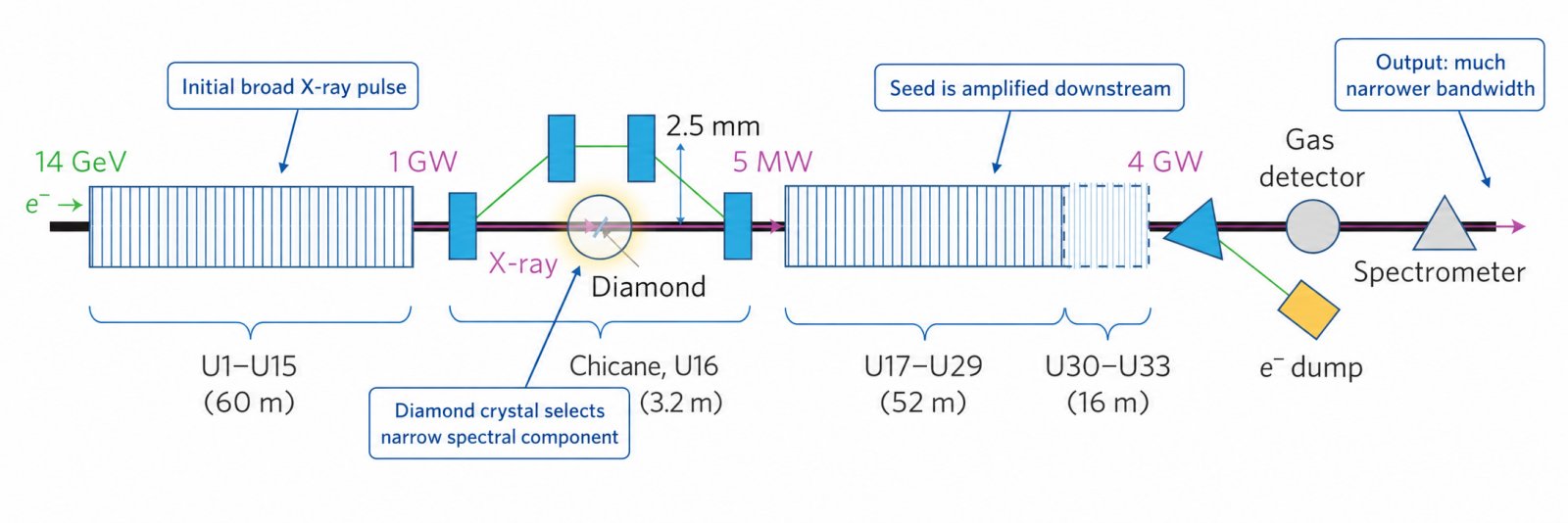
Figure 1. The diamond crystal selects a "seed" (a narrow spectral mode) from the initial SASE pulse, which is then amplified downstream.
At LCLS, self-seeding reduced the spectral bandwidth from about 20 eV to 0.4 eV — roughly 50× narrower.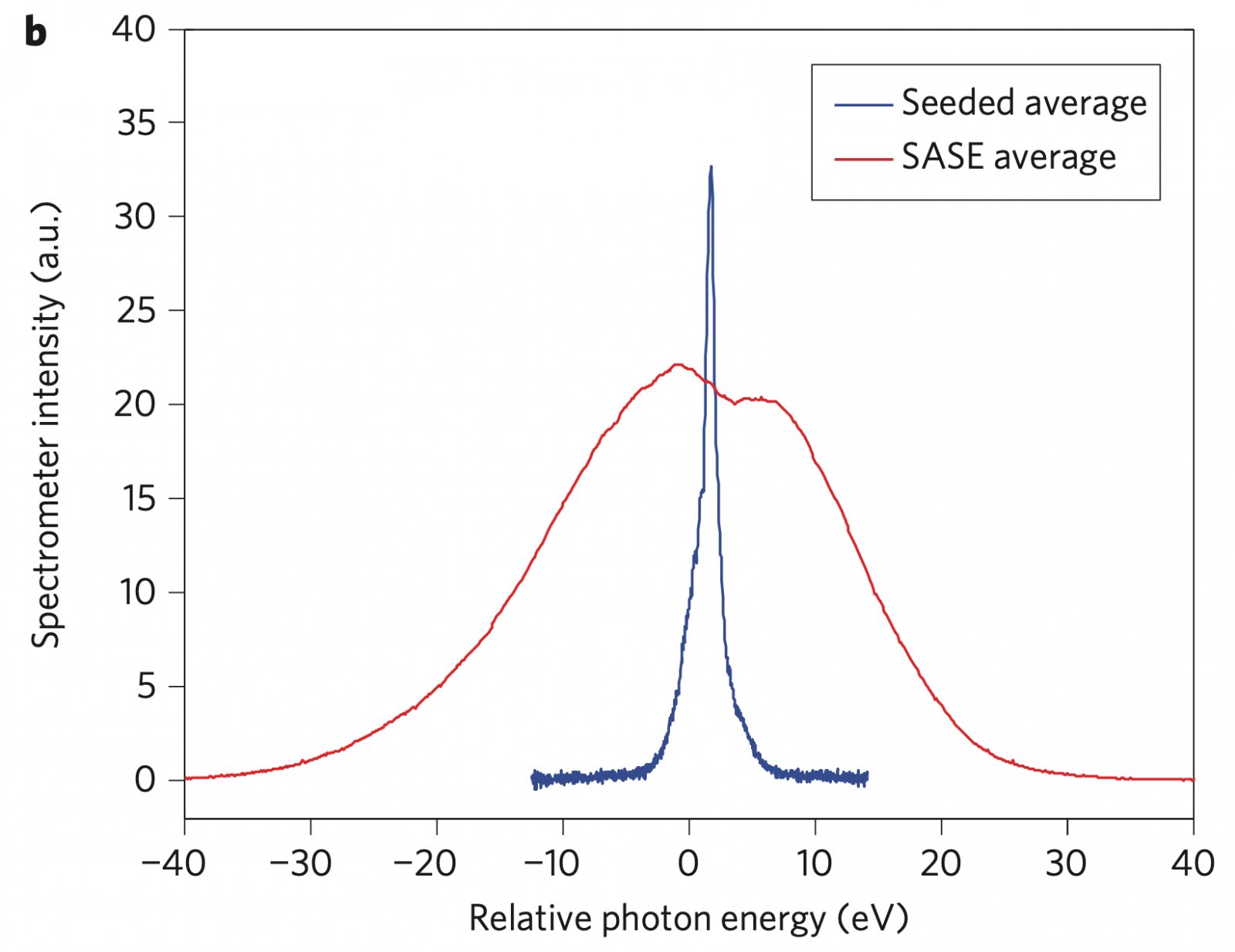
Figure 2. Self-seeding produces pulses with a much narrower X-ray spectrum than standard SASE pulses.
HXRSS worked well at LCLS, which operates at 120 Hz, because the low repetition rate leaves substantial time for the diamond crystal to thermally relax between pulses. However, the thermal issue dramatically worsens when the pulse repetition rate is pushed towards hundreds of kHz or MHz at LCLS-II or LCLS-II-HE. The time between pulses becomes much shorter, and residual heat can accumulate at the pulse footprint (only 27 μm in FWHM size). The localized heat produces a thermal bump/bulge with a non-flat surface and non-uniform lattice strain.
This perturbs the diamond crystal lattice, and with it the Bragg condition on which the monochromator operates. The thermal bump can shift or distort the transmitted seed spectrum and reduce its power. In severe cases, the seed becomes too weak to dominate the intrinsic FEL shot noise, and self-seeding fails.
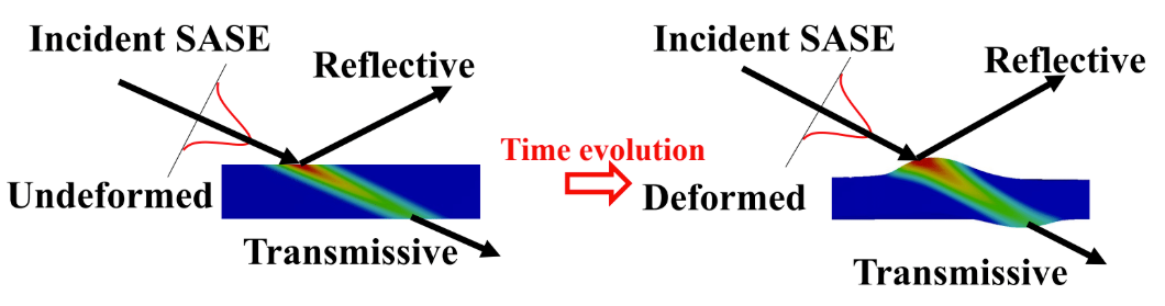
Figure 3. Thermal load deforms the diamond crystal and changes its interaction with the incident X-ray pulse.
The challenge is therefore:
How can we prevent an ultra-thin diamond crystal from thermally distorting under an intense, high-repetition-rate X-ray beam?
Problem solving: from vague to solvable
The challenge as stated is not yet a solvable problem. "Cool the crystal" is not well defined: how much cooling is needed? What deformation is acceptable? What should we measure to evaluate whether it works?
To make the problem solvable, we first need to know what must be characterized, modeled, measured, and controlled. If an important constraint is missed at this stage, the problem may look solved on paper but fail later in the real system.
I used the original photo shown to me even before I started this project and asked Pathon to generate a TIP from my LPQ graph.
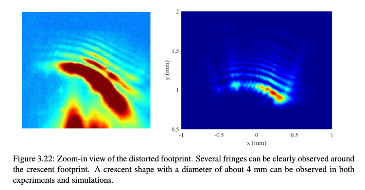
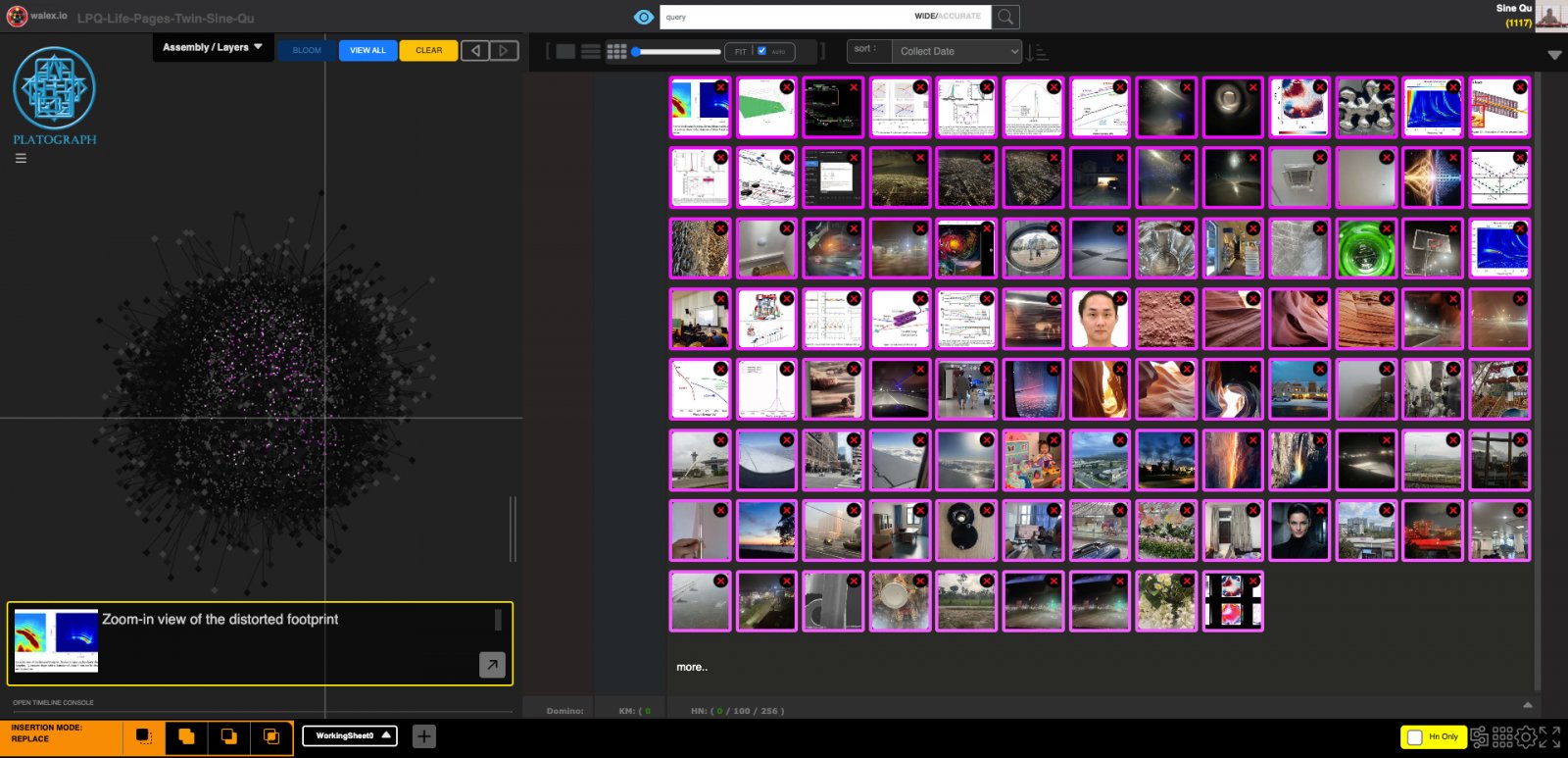
The TIP brings several aspects of the problem together (HN location is indicated by row and column number):
- Initial condition. HNs such as (4,8) and (4,5) point to defects, scratches and other imperfections. Before attributing any deformation to thermal load, the crystal's initial condition must be characterized. These HNs do not diagnose defects in the actual crystal; they raise the requirement that its initial state be measured.
- Operating principle. (2,13) brings us back to Bragg diffraction. Temperature and deformation matter because they change lattice spacing and orientation, and therefore the crystal's X-ray response.
- Core physics. (1,4) brings in energy deposition, electron-phonon thermalization and heat transfer. It also highlights the separation of timescales: diffraction is effectively instantaneous relative to thermal and structural evolution, so it can be evaluated against a frozen temperature/strain field.
- Transient stability. (1,12) and (3,13) point to Lamb waves and remind us that rapid heating can also generate transient mechanical waves/vibration, which must be checked rather than assumed negligible.
- Metrics. (1,9) and (3,6) point to footprint and wavefront distortion, while (5,12) brings in the spectrum and the XPP experimental environment.
- Compatibility. (4,2) shows the chamber and motion stages of HXRSS system, a reminder that the design must remain within the payload and motion limit of the existing motion stages.
Guided by these pieces, the challenge now becomes a specific problem:
Under practical HXRSS operating conditions, determine how XFEL energy deposition produces thermal and mechanical responses in the crystal, how these perturb its Bragg response, and how the resulting degradation appears in the spectrum, intensity, footprint and wavefront.
The physical chain is now explicit:
Energy deposition → heat transfer → residual temperature/strain → Bragg response to the next pulse → measurable X-ray performance
Once acceptable X-ray performance is specified by user requirements, this chain can also be worked backward to determine the thermal and mechanical requirements an engineering solution must meet.
The causal chain itself is domain physics; I am not claiming Platograph derived it. What the TIP shows is that, from the original input alone, it brings together the pieces the decomposition needs: initial condition, transient response, the right observables and the mechanical envelope of the existing system. Those "puzzle" pieces are enough to assemble a complete, solvable formulation rather than recalling the constraints one at a time.
Creativity emerging: think out of the box
A well-defined but hard problem raises the next question:
Where can possible solutions or new approaches come from?
Searching only within the HXRSS literature will mostly return solutions already familiar to the field. For creativity, I instead let Pathon search broadly across my LPQ, including daily-life material captured with no research problem in mind, for a full brainstorm in my experiences and knowledge space.
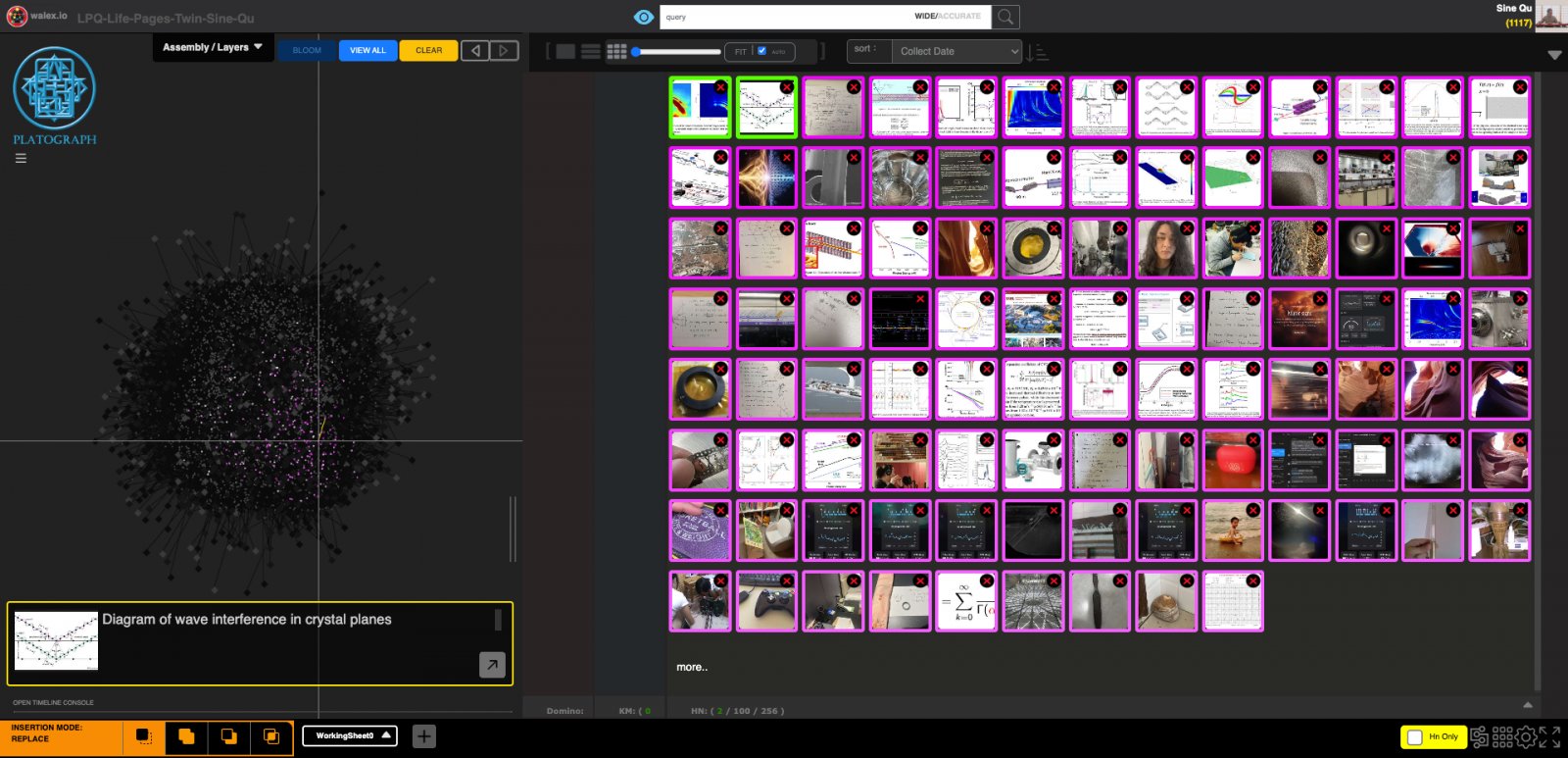
The TIP still retrieves directly related knowledge: Lamb waves, thermal waves, cracks and crystal diffraction. More interestingly, it also places seemingly unrelated HNs into the same context.
The clearest case is HN (7,12), a photograph of an old test tube from a silver-mirror experiment I kept from a chemistry class. I photographed it for no reason connected to X-ray optics, and it entered the LPQ the same way every other snapshot does. What the photograph shows is a thin metallic layer deposited on a transparent substrate. Next to a problem about extracting heat from a transparent crystal, that image reads differently than it does in a chemistry notebook.
A major thermal bottleneck in this design is the interface between the diamond and its holder. A metallized layer on the crystal offers a way to improve that interface without relying only on mechanical clamping.
This association points to the same metallized-interface direction that was later implemented as a sputtered-gold cryogenic mounting design in this project. I want to be exact about what that does and does not demonstrate. The TIP was generated after the fact and cannot have caused the design; what it shows is that Pathon can recover a relevant connection from an unrelated corner of the LPQ without being told where to look.
The direction eventually became a sputtered-gold layer with a thermocompression bond to the holder, and was later compared with indium solder and pure clamping. That comparison exposes the actual engineering tradeoff: strong thermal contact removes heat efficiently but can transmit strain into the crystal, while gentler mounting reduces strain but can compromise heat transfer.
Other connections in the same TIP include:
- Phase change. HNs showing condensation (2,10) and freezing (7,10) brought heat pipes and other phase-change cooling approaches to mind.
- From robotics to manufacturability. My previous robotics experience in (8,1) brings attention back to assembly and manufacturability. A thermally attractive concept is not useful if the thin crystal, holder and cooling interface cannot actually be fabricated and assembled reliably.
- From signal processing to new analysis methods. The wavelet analysis HN in (4,7) suggests analyzing the transient thermal response in the time-frequency domain, while (8,5), on the Mittag-Leffler function, points toward trying fractional-order descriptions. These are hypotheses to test, not assumed improvements.
- Adjacent but non-obvious. HN (3,2) brings back a layered diffraction model for an inhomogeneously deformed crystal, another way to connect a non-uniform strain field to the resulting diffraction response.
Not all of these survived. The fractional-order models remain untested.
A brainstorm is useful if it produces candidates worth checking, not if every candidate turns out to be correct.
What's important is that the HNs above came from different times, subjects and experiences rather than being collected for this HXRSS problem. When Platograph places them next to a well-defined problem, some become connections I would not have searched for directly.
Defined problem + broad personal knowledge → unexpected connections → new hypotheses
Decision making: finalizing solutions
Creative ideas have to be consolidated into an implementable solution:
What should we actually build? What requirement specifications must the solution satisfy, and what functional specifications must it deliver?
For this TIP, I started from a real photo of the existing LCLS HXRSS system, HN (1,3). This is arguably the most important input, because LCLS-II-HE HXRSS is not a brand new device: it is an upgraded counterpart that must fit into the existing real beamline.
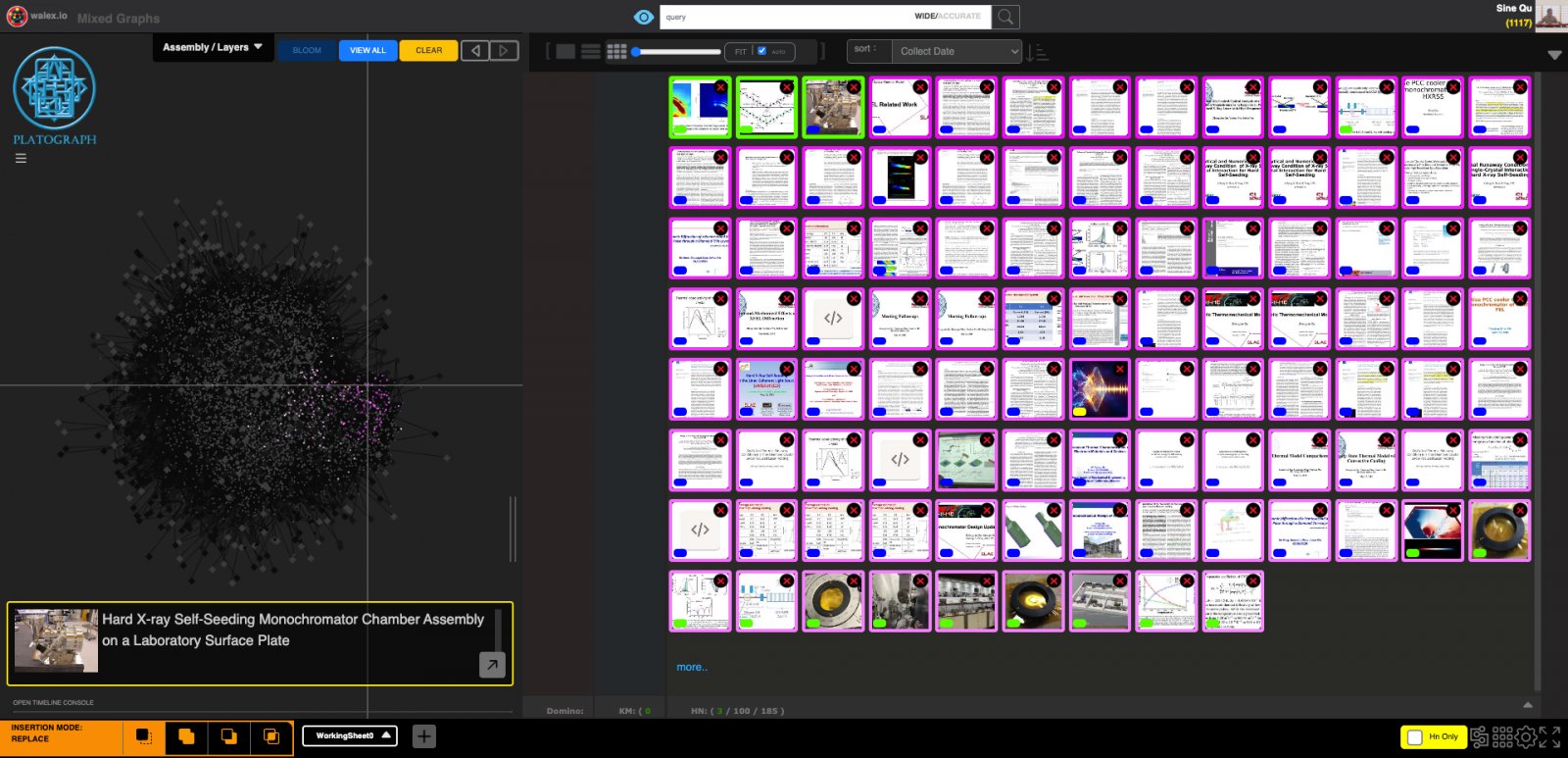
The TIP brings together the layers of information those decisions require.
- Interfaces that must be preserved. The original LCLS HXRSS paper in (1,5) and system layout in (1,11) define the legacy to preserve: optical configuration, available space, UHV compatibility, motion, beam transport, flanges, bellows and other interfaces (i.e., ion pump connection). HXRSS systems at EuXFEL (5,13), (6,1), SACLA (7,8) and PAL-XFEL (5,6) show how other facilities approached related problems, even though none of them have active cooling system.
- What the upgrade has to deliver. The LCLS-II-HE specifications in (3,3), (7,2), (7,3) and (7,4) define what the new system must deliver: photon-energy range, repetition rate, beam conditions, seed performance and cooling capacity.
- Operating temperature: a window, not the minimum. The thermal-runaway HNs in (2,9), (2,10) and (2,13), together with diamond thermal properties in (4,1), (6,3) and (8,8), constrain the operating-temperature window rather than simply pushing it as low as possible. Thermal conductivity, thermal expansion, thin-film effects and radiative load all matter. The PCC cryocooler manual in (1,12) adds cooling capacity, achievable temperature and vibration information for comparison with a liquid-nitrogen system.
- Repetition rate: derived backward from a seed-performance criterion. My earlier simulations in (3,4) and (3,8) connect temperature and strain to seed energy, bandwidth and power. The 2020 study showed how a chosen seed-performance criterion can be worked backward into an allowable recovery time and repetition rate.
- Heat pipe: attractive, then rejected on vibration and integration. A heat pipe is attractive as a highly efficient passive phase-change device. In this system it was screened out once the required cryogenic regime, integration and vibration isolation were considered together: a rigid metallic transfer path would couple the crystal mechanically to the cooler head.
- Diamond: HPHT selected over CVD. HNs (2,11), (3,10) and (3,11) compare CVD and HPHT diamond. CVD could not meet the required optical quality, so HPHT was selected despite cost and lead-time implications.
- Crystal acceptance: an initial Bragg response before installation. The RCI results in (7,12) and crystal HNs in (7,13), (8,3) and (8,6) provide an acceptance step: the actual vendor crystal must demonstrate an acceptable initial Bragg response before installation.
- Thermal interface: gold thermocompression, later compared with indium and clamping. HN (3,9) brings in indium solder as another thermal-interface option, continuing the direction opened by the gold thermocompression design. Strong thermal contact improves heat removal but can introduce unacceptable strain, while gentler mounting can compromise heat transfer. Later work comparing clamping, soldering and hybrid approaches quantified this tradeoff.
- Validation plan: transient waves checked, then beamline validation. The transient-wave study in (6,6) helps determine whether thermoelastic waves materially affect the design or can be treated as secondary under the relevant conditions. The experimental proposal in (7,11) defines the beamline validation at XPP using real X-ray observables.
The decision process becomes:
User requirements → system constraints → physical operating window → candidate screening → material and component choices → acceptance testing → beamline validation
None of these HNs is individually a discovery. Their value here is that they put the relevant constraints in one place while decisions are being made. For example, operating temperature cannot be chosen from thermal conductivity alone; thermal expansion, thin-film behavior, radiative load and cooler vibration all affect the choice.
As a component inside a much larger complex system, HXRSS cooling cannot be decided by picking the cooling method with the highest heat-transfer performance. Every candidate has to satisfy optical, thermal, mechanical, vacuum, integration, cost and experimental constraints at the same time.
Problem Solving defines what must be solved. Creativity Emerging expands what might work. Decision Making narrows those possibilities into what can actually be built.
Scope and limitations
- This is one case reconstructed after the fact. The TIPs did not run the project; they were asked whether they could recover the relevant material from the LPQ as it stood at the time.
- Everything captured after my part of the project ended in 2021 was avoided from the TIP input even if they were extracted, except the 2024 hybrid mounting paper.
- In all three TIPs, a human selected which returned HNs to act on. Platograph retrieves and juxtaposes; it does not make the engineering decision.
- Because I already knew the outcome, I cannot fully separate recognizing a connection from re-recognizing one I had made before. A prospective TIP on an open problem would be the stronger next demonstration.
Backup: a more detailed technical version.
In an XFEL, electrons are **photoemitted from a photocathode** by a pulsed optical laser and introduced into the linear accelerator (linac) at SLAC. They are accelerated and compressed in the linac and bunch compressors to form a dense electron bunch, then transported under ultra-high vacuum (about 1 × 10⁻⁹ torr or 1 × 10⁻⁷ Pa) through the beam switchyard to the hard X-ray undulator hall.
Passing through the undulator, which consists of alternating magnetic structures, the electron beam oscillates transversely and emits X-ray radiation. **When the electron energy and undulator parameters satisfy the resonance condition, the radiation is amplified along the undulator.** This is Self-Amplified Spontaneous Emission (SASE).
SASE delivers very high peak power, but its bandwidth is comparatively broad — on the order of 20 eV at LCLS photon energies — with poor longitudinal coherence. A beam with comparable pulse energy but much narrower bandwidth is needed for many experiments, and this cannot simply be achieved by adding a downstream monochromator because most of the pulse energy would be discarded. HXRSS is a single-pass self-seeding approach compatible with the existing beamline; cavity-based schemes such as XFELO and CB-XFEL pursue related goals through different architectures.
In HXRSS mode, a transmissive monochromator — a 110 μm thick type IIa HPHT diamond crystal with a **qualified low-defect working area** — filters the SASE spectrum and produces a narrow-band seed before the main downstream amplification. The seed then interacts with the electron beam in the following undulator sections and is amplified into an X-ray pulse with roughly 50× narrower bandwidth.
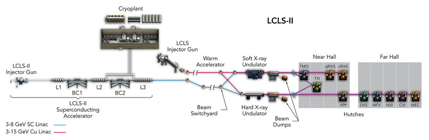
LCLS uses a warm copper linac and operates at 120 Hz. LCLS-II and LCLS-II-HE use a superconducting RF linac and can theoretically operate at much higher repetition rates, up to the MHz range. The thermal challenge for the transmissive monochromator therefore becomes much more severe.
Without sufficient cooling, the highly localized deposited heat (over a footprint of only about 27 μm FWHM in the case considered here) accumulates between pulses and produces a local thermal bump. The resulting temperature, strain and deformation disturb the Bragg response and weaken the seed. If the seed becomes too weak to dominate the FEL shot noise, self-seeding fails.
A related problem appears downstream, where a reflective silicon monochromator can also deform thermally, degrading the footprint, wavefront and transmitted pulse energy.